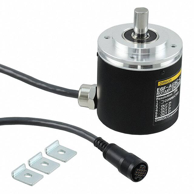
Absolute 60-mm-dia. Rotary Encoder
E6F-A
CSM_E6F-A_DS_E_7_4
Rugged Rotary Encoder
• Absolute model.
• External diameter of 60 mm.
• Resolution of up to 1,024 (10-bit).
• IP65 oil-proof protection.
• Strong shaft.
Radial: 120 N, Thrust: 50 N
For the most recent information on models that have been certified for
safety standards, refer to your OMRON website.
Be sure to read Safety Precautions on
page 5.
Ordering Information
Encoders [Refer to Dimensions on page 6.]
Power supply
voltage
Output
configuration
Output
code
Resolution
(divisions)
5 to 12 VDC
NPN open collector
BCD
360
PNP open collector
12 to 24 VDC
256, 360, 720
NPN open collector
Gray
code
256, 360, 720, 1,024
Connection method
Pre-wired Model
Pre-wired Connector
Model (2 m)
Pre-wired Model
Pre-wired Connector
Model (2 m)
Pre-wired Model
Pre-wired Connector
Model (2 m)
Pre-wired Model
PNP open collector
Model
E6F-AB3C 360P/R 2M *2
E6F-AB3C-C 360P/R 2M *2
E6F-AB5C 360P/R 2M
E6F-AB5C-C 360P/R 2M
E6F-AB5B 360P/R 2M
E6F-AG5C-C (resolution) 2M *1
Example: E6F-AG5C-C 256P/R 2M
E6F-AG5C (resolution) 2M
Example: E6F-AG5C 256P/R 2M
E6F-AG5B (resolution) 2M
Example: E6F-AG5B 256P/R 2M
*1. The E6F-AG5C-C is designed for connection to Cam Positioners (H8PS).
*2. Models are also available with 5-m cables.
Accessories (Order Separately)
[Dimensions: Refer to Accessories for coupling dimensions and to page 6 for the dimensions of other accessories.]
Name
Couplings
Model
E69-C10B
Remarks
Provided with E6F Pre-wired Models.
E69-C610B
Different end diameter
E69-C10M
Metal construction
Servo Mounting Bracket
E69-2
Provided with the product. (Three brackets in a set.)
Extension Cable
E69-DF5
E69-DF10
E69-DF20
5m
10 m
20 m
Models are also available with 15-m and 98-m cables.
Refer to Accessories for details.
1
�E6F-A
Ratings and Specifications
Model E6FAB3C-C
Item
E6FAB3C
E6FAB5C-C
E6FAB5C
E6FAB5B
E6FAG5C-C
Power supply voltage
5 VDC −5% to 12 VDC
12 VDC −10% to 24 VDC +15%, ripple (p-p): 5% max.
+10%, ripple (p-p): 5% max.
Current consumption*1
60 mA max.
Resolution
(pulses/rotation)*2
360
Output code
BCD
256, 360,
720
E6FAG5C
256, 360, 720, 1024
Gray code
NPN open-collector output
PNP opencollector
output
Output capacity
Applied voltage: 30 VDC max.
Sink current: 35 mA max.
Residual voltage: 0.4 V max. (at sink current of 35 mA)
Source current: 35 mA
max.
Residual
voltage:
0.4 V max.
(at source
current of
35 mA)
Maximum response
frequency*3
10 kHz
Logic
Negative logic (high = 0, low = 1)
Direction of rotation
Output code incremented by CW (as viewed from the end of the shaft)
Rise and fall times of
output
1 μs max. (E6F-AB3C, A@5C: Load voltage: 5 V, Load resistance: 1 kΩ, Output cable: 2 m max.;
E6F-A@5B: Power supply voltage: 12 V, Load resistance: 1 kΩ, Output cable: 2 m max.)
Starting torque
9.8 mN·m max. at room temperature, 14.7 mN·m max. at low temperature
Output configuration
NPN open-collector output
PNP opencollector
output
Applied voltage: 30 VDC
max.
Sink current: 35 mA max.
Residual voltage: 0.4 V
max.
(at sink current of 35 mA)
Source current: 35 mA
max.
Residual
voltage:
0.4 V max.
(at source
current of
35 mA)
20 kHz
Positive logNegative logic (high = 0,
ic (high = 1,
low = 1)
low = 0)
Positive logic (high = 1,
low = 0)
1.5 × 10⁻⁶ kg·m2 max.
Moment of inertia
Shaft
loading
E6FAG5B
Radial
120 N
Thrust
50 N
Maximum permissible
speed
5000 r/min
Ambient temperature
range
Operating: −10 to 70°C (with no icing), Storage: −25 to 80°C (with no icing)
Ambient humidity range
Operating: 35% to 85% (with no condensation), Storage: 35% to 95% (with no condensation)
Insulation resistance
20 MΩ min. (at 500 VDC) between current-carrying parts and case
Dielectric strength
500 VAC, 50/60 Hz for 1 min between current-carrying parts and case
Vibration resistance
10 to 500 Hz, 2-mm double amplitude for 11 min 3 times each in X, Y, and Z directions
Shock resistance
Destruction: 1,000 m/s2 3 times each in X, Y, and Z directions
Degree of protection
IEC 60529 IP65, in-house standards: oilproof
Connection method
Connector
Models
(Standard
cable length:
2 m)
Material
Case: Zinc alloy, Main unit: Aluminum, Shaft: SUS420J2, Mounting Bracket: Galvanized iron
Weight (packed state)
Approx. 500 g
Accessories
Servo Mounting Bracket, Coupling (provided with Pre-wired Models only), Hexagonal wrench (provided with Prewired Models only), Instruction manual
Pre-wired
Models
(Standard
cable length:
2 m)
Connector
Models
Pre-wired Models (Stan(Standard
dard cable length: 2 m)
cable length:
2 m)
Connector
Models
Pre-wired Models (Stan(Standard
dard cable length: 2 m)
cable length:
2 m)
*1. An inrush current of approximately 9 A will flow for approximately 5 μs when the power is turned ON.
*2. The code is as follows:
Output code
BCD
Gray code
Resolution
360
256
360
720
1024
Code No.
0 to 359
0 to 255
76 to 435 (gray after 76)
152 to 871 (gray after 152)
0 to 1023
*3. The maximum electrical response speed is determined by the resolution and maximum response frequency as follows:
Maximum response frequency
× 60
Resolution
* This means that the Rotary Encoder will not operate electrically if its speed exceeds the maximum electrical response speed.
Maximum electrical response speed (rpm) =
2
�E6F-A
I/O Circuit Diagrams
Model
Output Circuits
Output mode
5 to 12 VDC
E6F-A
main
circuit
E6F-AB3C
E6F-AB3C-C
Output
35 mA max.
30 VDC max.
0V
Shield
GND
Note: The circuit is the same for all bit
outputs.
Each E6F-A Rotary Encoder has
one main circuit.
Direction of rotation: CW (as viewed from end of shaft)
1˚±0.5˚
ON
OFF
ON
1
2
OFF
ON
2
2
OFF
ON
3
2
OFF
ON
0
2 × 10
OFF
ON
1
2 × 10
OFF
ON
2
2 × 10
OFF
ON
3
2 × 10
OFF
ON
0
2 × 100
OFF
ON
1
2 × 100
OFF
0 1 2 3 4 5 6 7 8 9 10 11 12 13 14 15 16 17 18 19 20 21 22
Address
2
12 to 24 VDC
E6F-A
main
circuit
E6F-AB5C
E6F-AB5C-C
Output
35 mA max.
30 VDC max.
0V
Shield
GND
Note: The circuit is the same for all bit
outputs.
Each E6F-A Rotary Encoder has
one main circuit.
12 to 24 VDC
E6F-A
main
circuit
0
Output
35 mA
max.
E6F-AB5B
Shield
0V
GND
Note: The circuit is the same for all bit
outputs.
Each E6F-A Rotary Encoder has
one main circuit.
12 to 24 VDC
E6F-A
main
circuit
E6F-AG5C
E6F-AG5C-C
Output
35 mA max.
30 VDC max.
0V
Output
transistor
ON
OFF
1 ON
2
OFF
2 ON
2
OFF
3 ON
2
OFF
4 ON
2
OFF
5 ON
2
OFF
6 ON
2
OFF
7 ON
2
OFF
8 ON
2
OFF
9 ON
2
OFF
Address
Direction of rotation: CW (as viewed from end of shaft)
0
2
Shield
GND
Note: The circuit is the same for all bit
outputs.
Each E6F-A Rotary Encoder has
one main circuit.
12 to 24 VDC
E6F-A
main
circuit
Output
35 mA
max.
E6F-AG5B
Shield
0V
GND
0 1 2 3 4 5 6 7 8 9 10 11 12 13 14 15 16 17 18 19 20 21 22 23 24 25 26 27 28 29 30 31 32 33 34 35 36 37 38 39 40 41 42 43 44 45 46 47 48 49 50 51 52 53 54 55 56 57 58 59 60 61 62 63 64 65
Note: The circuit is the same for all bit
outputs.
Each E6F-A Rotary Encoder has
one main circuit.
3
�E6F-A
Connection Specifications
Connector Models*
Model
Pre-wired Model
E6F-AB3C-C/
-AB5C-C
E6F-AG5C-C
Output signal
Output signal
Pin
No.
10-bit (360)
1
20
2
21
3
22
25
4
23
5
8-bit (256)
9-bit (360)
Model
10-bit (720)
E6F-AB3C/
-AB5C/-AB5B
E6F-AG5C/-AG5B
Output signal
Output signal
Wire
color
10-bit (360)
8-bit (256)
9-bit (360)
10-bit
(720,1024)
29
Brown
20
20
20
20
28
Orange
21
21
21
21
25
25
Yellow
22
22
22
22
21
21
21
Green
23
23
23
23
20 × 10
20
20
20
Blue
20 × 10
24
24
24
6
2 × 10
2
7
7
7
2
Purple
2 × 10
2
5
5
25
7
22 × 10
24
24
24
Gray
22 × 10
26
26
26
8
23 × 10
22
22
22
White
23 × 10
27
27
27
9
20 × 100
23
23
23
Pink
20 × 100
Not connected
28
28
10
21 × 100
26
26
26
Light
blue
21 × 100
Not connected Not connected
1
11
Connected in- Not connected
ternally
28
2
Shield (ground)
---
12
-AB3C-C: 5 to
12 VDC, -AB5CC: 12 to 24 VDC
12 to 24 VDC
13
0 V (common)
0 V (common)
Red
1
Shield (ground)
29
Shield (ground)
-AB3C: 5 to
12 VDC, -AB5C:
12 to 24 VDC
12 to 24 VDC
0 V (common)
0 V (common)
Black
* Connector: RP13A-12PD-13SC (Hirose Electric Co., Ltd.)
Note: Normally connect GND to 0 V or to an external ground.
2
Connection Example
H8PS Cam Positioner Connection
Ordering Information
Model
E6F-AG5C-C
H8PS-8A
H8PS-8AP
H8PS-8AF
H8PS-8AFP
H8PS-16A
H8PS-16AP
H8PS-16AF
H8PS-16AFP
H8PS-32A
H8PS-32AP
H8PS-32AF
H8PS-32AFP
Specifications
Rated voltage
24 VDC
Cam precision
0.5° (for 720 resolution), 1° (for 256/360 resolution)
No. of output
points
8-point output type:
8 cam outputs, 1 RUN output, 1 pulse output
16-point output type:
16 cam outputs, 1 RUN output, 1 pulse output
32-point output type:
32 cam outputs, 1 RUN output, 1 pulse output
Encoder
response
RUN mode, test mode:
256/360 resolution ...1,600 r/min max. (1,200 r/min when
advance compensation is set for four cams or more)
720 resolution ..........800 r/min max. (600 r/min when advance compensation is set for four cams or more)
Additional
functions
• Origin compensation (zeroing)
• Rotation direction switching
• Angle display switching
• Teaching
• Pulse output
• Angle/number of rotations display switching
• Puncture *
• Angle advance
• Number of rotations alarm output
• Setting with support software (order separately) *
Note: For 16-point and 32-point output types only
4
�E6F-A
Safety Precautions
Refer to Warranty and Limitations of Liability.
WARNING
This product is not designed or rated for ensuring
safety of persons either directly or indirectly.
Do not use it for such purposes.
Precautions for Correct Use
Do not use the Encoder under ambient conditions that exceed the
ratings.
● Adjustment
Reading the Output Code
Read the code after the LSB (output 20) of the code changes for the
E6F-AB3C and E6F-AB3C-C.
● Wiring
Spurious pulses may be generated when power is turned ON and
OFF. Wait at least 0.1 s after turning ON the power to the Encoder
before using the connected device, and stop using the connected
device at least 0.1 s before turning OFF the power to the Encoder.
Also, turn ON the power to the load only after turning ON the power
to the Encoder.
5
�E6F-A
(Unit: mm)
Dimensions
Tolerance class IT16 applies to dimensions in this datasheet unless otherwise specified.
Encoder
E6F-AB3C
E6F-AB5C
E6F-AG5C
E6F-AG5B
E6F-AB5B
(85)
60
Four, M3 holes;
Depth: 6
5
20
15
3
3
48 dia.
1 max.
54 dia.
0
dia. 1
60 dia. 40 -0.025
0
dia.
10 -0.015
14 max.
* 6-dia. oil-resistant PVC-insulated shielded
cable with 12 conductors (Conductor cross
section: 0.2 mm2, Insulator diameter: 1.1 mm),
Standard length: 2 m
17
The E69-C10B Coupling is provided.
E6F-AB3C-C
E6F-AB5C-C
E6F-AG5C-C
*
42.5
(85)
60
5
20
Four, M3 holes;
Depth: 6
48 dia.
1 max.
15
3
3
54 dia.
0
dia. 1
60 dia. 40 -0.025
0
dia.
10 -0.015
14 max.
* 1. 6-dia. oil-resistant PVC-insulated shielded
42.5
cable with 12 conductors (Conductor cross
section: 0.2 mm2, Insulator diameter: 1.1 mm),
Standard length: 2 m
*2. Connects to H8PS Cam Positioner (Hirose
Electric Co., Ltd.: RP13A-12PD-13SC).
17
The E69-C10B Coupling is sold separately.
*1
*2
16.9 dia.
2,000
37
Accessories (Order Separately)
Servo Mounting Bracket
E69-2
Mounting Bracket Installation
Panel
2
5.5-dia. Hole
120˚
(18)
16
120˚
9
Two, C1
40 dia.
120˚
3.1+0.1
0
8
16
72±0.2 dia.
(5.1)
Note: Provided with the product.
Three, M5
Extension Cable
E69-DF5
39.6
16.9 dia.
5,000
37
16.9 dia.
*2
*1
*3
*1. 6-dia. shielded cable with 12 conductors (Conductor cross section: 0.2 mm2,
Insulator diameter: 1.1 mm), Standard length: 5 m
*2. Connects to connector on E6F-AB@C-C or E6F-AG5C-C.
*3. Connects to H8PS Cam Positioner.
Note: 1. The E69-DF5 (5 m) is also
available with the following cable
lengths: 10 m, 15 m, 20 m, and
98 m.
2. Cable can be extended to 100 m
when the H8PS Cam Positioner
is connected.
Couplings
E69-C10B
E69-C610B
E69-C10M
Refer to Accessories for details.
6
�Terms and Conditions Agreement
Read and understand this catalog.
Please read and understand this catalog before purchasing the products. Please consult your OMRON representative if you
have any questions or comments.
Warranties.
(a) Exclusive Warranty. Omron’s exclusive warranty is that the Products will be free from defects in materials and workmanship
for a period of twelve months from the date of sale by Omron (or such other period expressed in writing by Omron). Omron
disclaims all other warranties, express or implied.
(b) Limitations. OMRON MAKES NO WARRANTY OR REPRESENTATION, EXPRESS OR IMPLIED, ABOUT
NON-INFRINGEMENT, MERCHANTABILITY OR FITNESS FOR A PARTICULAR PURPOSE OF THE PRODUCTS. BUYER
ACKNOWLEDGES THAT IT ALONE HAS DETERMINED THAT THE
PRODUCTS WILL SUITABLY MEET THE REQUIREMENTS OF THEIR INTENDED USE.
Omron further disclaims all warranties and responsibility of any type for claims or expenses based on infringement by the
Products or otherwise of any intellectual property right. (c) Buyer Remedy. Omron’s sole obligation hereunder shall be, at
Omron’s election, to (i) replace (in the form originally shipped with Buyer responsible for labor charges for removal or
replacement thereof) the non-complying Product, (ii) repair the non-complying Product, or (iii) repay or credit Buyer an amount
equal to the purchase price of the non-complying Product; provided that in no event shall Omron be responsible for warranty,
repair, indemnity or any other claims or expenses regarding the Products unless Omron’s analysis confirms that the Products
were properly handled, stored, installed and maintained and not subject to contamination, abuse, misuse or inappropriate
modification. Return of any Products by Buyer must be approved in writing by Omron before shipment. Omron Companies shall
not be liable for the suitability or unsuitability or the results from the use of Products in combination with any electrical or
electronic components, circuits, system assemblies or any other materials or substances or environments. Any advice,
recommendations or information given orally or in writing, are not to be construed as an amendment or addition to the above
warranty.
See http://www.omron.com/global/ or contact your Omron representative for published information.
Limitation on Liability; Etc.
OMRON COMPANIES SHALL NOT BE LIABLE FOR SPECIAL, INDIRECT, INCIDENTAL, OR CONSEQUENTIAL DAMAGES,
LOSS OF PROFITS OR PRODUCTION OR COMMERCIAL LOSS IN ANY WAY CONNECTED WITH THE PRODUCTS,
WHETHER SUCH CLAIM IS BASED IN CONTRACT, WARRANTY, NEGLIGENCE OR STRICT LIABILITY.
Further, in no event shall liability of Omron Companies exceed the individual price of the Product on which liability is asserted.
Suitability of Use.
Omron Companies shall not be responsible for conformity with any standards, codes or regulations which apply to the
combination of the Product in the Buyer’s application or use of the Product. At Buyer’s request, Omron will provide applicable
third party certification documents identifying ratings and limitations of use which apply to the Product. This information by itself
is not sufficient for a complete determination of the suitability of the Product in combination with the end product, machine,
system, or other application or use. Buyer shall be solely responsible for determining appropriateness of the particular Product
with respect to Buyer’s application, product or system. Buyer shall take application responsibility in all cases.
NEVER USE THE PRODUCT FOR AN APPLICATION INVOLVING SERIOUS RISK TO LIFE OR PROPERTY OR IN LARGE
QUANTITIES WITHOUT ENSURING THAT THE SYSTEM AS A WHOLE HAS BEEN DESIGNED TO ADDRESS THE RISKS,
AND THAT THE OMRON PRODUCT(S) IS PROPERLY RATED AND INSTALLED FOR THE INTENDED USE WITHIN THE
OVERALL EQUIPMENT OR SYSTEM.
Programmable Products.
Omron Companies shall not be responsible for the user’s programming of a programmable Product, or any consequence
thereof.
Performance Data.
Data presented in Omron Company websites, catalogs and other materials is provided as a guide for the user in determining
suitability and does not constitute a warranty. It may represent the result of Omron’s test conditions, and the user must correlate
it to actual application requirements. Actual performance is subject to the Omron’s Warranty and Limitations of Liability.
Change in Specifications.
Product specifications and accessories may be changed at any time based on improvements and other reasons. It is our
practice to change part numbers when published ratings or features are changed, or when significant construction changes are
made. However, some specifications of the Product may be changed without any notice. When in doubt, special part numbers
may be assigned to fix or establish key specifications for your application. Please consult with your Omron’s representative at
any time to confirm actual specifications of purchased Product.
Errors and Omissions.
Information presented by Omron Companies has been checked and is believed to be accurate; however, no responsibility is
assumed for clerical, typographical or proofreading errors or omissions.
2019.4
In the interest of product improvement, specifications are subject to change without notice.
OMRON Corporation
Industrial Automation Company
http://www.ia.omron.com/
(c)Copyright OMRON Corporation 2019 All Right Reserved.
�